Animation Graph Editor
If you double click on an animation graph in the console, the animation graph editor will open.
The Animation Graph Editor is where you edit your animation graph. An animation graph will output a pose at each frame, and this is where you will define the logic of how it does so. The Animation Graph Editor is composed of different tabs: Details, State Editor, State Machine Editor, Animation Controller Input Editor, Animation Set Editor, Blend Space Editor, Bone Mask Editor and Animation Graph Description. It all starts (and ends!) in the State Editor, with the “Root” state, which outputs your final pose.
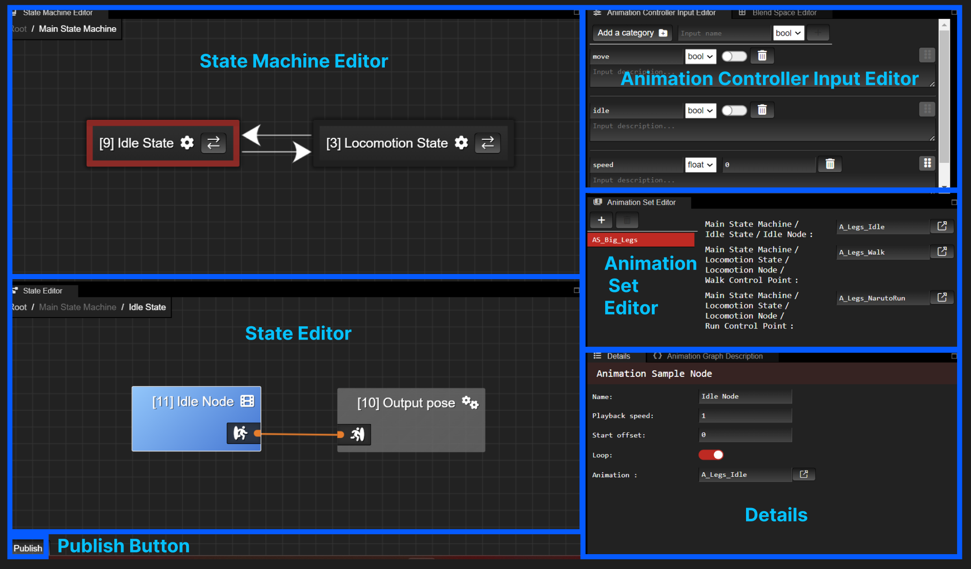
Animation Graph Editor Tabs
Publish Button
To save your animation graph, press the Publish button.
If publishing succeeded, you’ll get a green notification on the bottom right.
If publishing failed, you’ll get a red notification. The publishing error will be shown in the Animation Graph Description tab.
Examples of publishing errors:
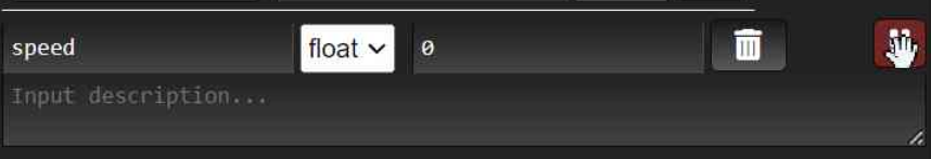
- Var node <input name> (<input id>) is referencing an unknown attribute of the input descriptor.
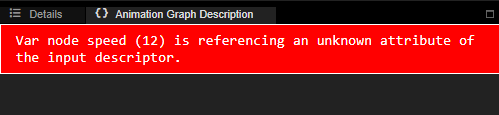
This signifies that you have an input (in the example above the input named speed) which you use in your State Editor but that you deleted from your Animation Controller Input Editor. To fix the error, simply delete all those input nodes in your State Editor and republish.
- State machine ID <state machine id> (<state machine name>) does not have an entrypoint
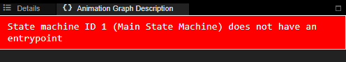
This signifies that your state machine (in the example above the state machine named Main State Machine) does not have an entrypoint state. To fix the error, specify a state as entrypoint in your state machine and republish.
- If you have any other publishing errors, do not hesitate to reach out to us in our community page.
Details
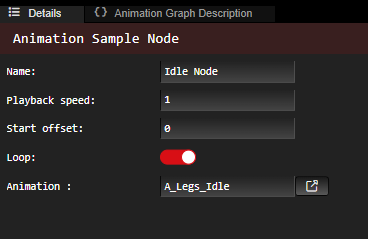
Select a node, state, or transition and you can see and edit the details of it. For a simple Animation Sample Node, the details include the playback speed. the start offset (expected to be between 0.0 and 1.0), the animation in question, etc.
State Editor
The state editor is where you edit a state of your animation graph. Each animation graph is composed of a state called “Root” which is the starting point of your animation graph.
A state is composed of nodes. The purpose of a state is to create a pose.
See more info on the nodes you can create here.
![[object Object]](/images/docs/bbf6444f-c620-49a7-96c2-52cfaf15d22d/Untitled-4e651536-f502-431d-bc72-dde9fff0d224.png)
![[object Object]](/images/docs/bbf6444f-c620-49a7-96c2-52cfaf15d22d/Untitled-bd5f50bb-1e1d-42f8-9087-6f064fd12c1d.png)
Each state is composed of an output pose node. What is connected to the output pose node is the resulting pose of that state.
You can see which state your editing by looking at the path of your state on the top left. In the example above we are editing the state named “Idle State”. To go back to a previous state in the path, like the state called “Root”, click on it in the path.
When you select a state machine node, the state machine will open in the State Machine Editor above the State Editor. You can then modify the states of that state machine.
State Editor Actions:
Move Around
To move around, hold RMB or Mouse Scroll within your state editor and move your mouse.
To zoom in and out, scroll your mouse.
Create Node
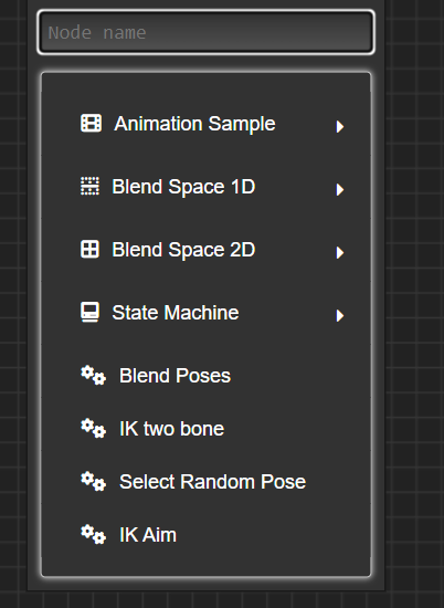
Right click on where you to create your node. The nodes that you can create will appear in a drop down menu. For Animation Sample, Blend Space nodes, and State Machine, you will also need to specify the name of your node.
See more info on the nodes you can create here.
Edit Node Details
Click on the node. You will see the node details that you can edit in the Details tab.
Connect Nodes
Drag the output of a node to the input of the next node. The input type and output type need to match.
![[object Object]](/images/docs/36a76d11-b824-4164-86c8-5c5d01110f9c/Untitled-4079fdb0-ed55-4a17-b90e-9c8ed16bdaaa.png)
![[object Object]](/images/docs/36a76d11-b824-4164-86c8-5c5d01110f9c/Untitled-b0daeae7-78e1-4d19-a2b8-c5a04eb37d03.png)
Delete Transition Between Nodes
Select the connection and press Delete.
Delete Node
Click on the node you want to delete and then press ‘Delete’.
You cannot delete an Output Pose node.
State Machine Editor
The state machine editor is where you edit a state machine node of your animation graph.
A state machine is composed of states. Each state machine has an entrypoint state which is the state outlined in red. The starting point of a state machine is the entrypoint state.
![[object Object]](/images/docs/bbf6444f-c620-49a7-96c2-52cfaf15d22d/Untitled-1a97796d-5da2-4d27-b319-15846a2aed71.png)
To go back to previous state machines, use the path on the top left.
When you select a state, the state will open in the State Editor below. You can then modify the nodes of that state.
State Machine Editor Actions:
Move Around
- To move around, hold RMB or Mouse Scroll within your state editor and move your mouse.
- To zoom in and out, scroll your mouse.
Create State
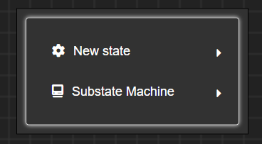
Right click, select “New state” and specify the state name.
Make State Entrypoint
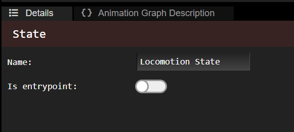
Click on the state and toggle “Is entrypoint” in the Details tab. You can also rename the state here.
Delete State
- Click on the state then press Delete.
Create Transition Between States
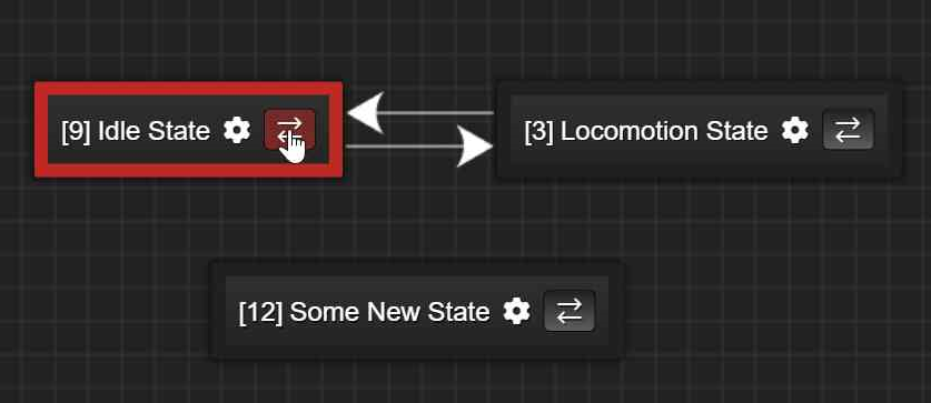
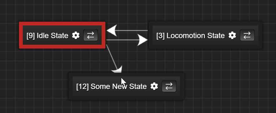
Click on the arrows button of a state and then click on the state you want it to transition to.
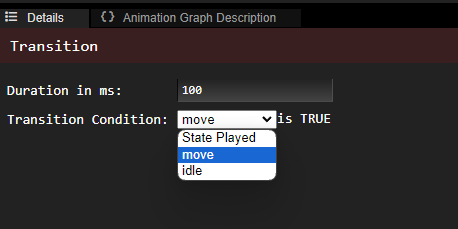
Edit Transition
Click on the transition and then edit it in the Details tab.
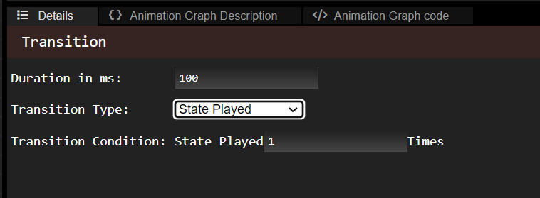
You can modify the duration of the transition (i.e. how long does it to take to transition from the previous state to the next).
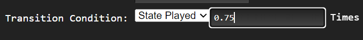
You can also modify the transition type. There are three different transition types:
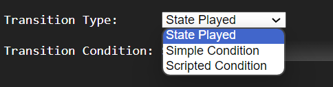
State Played X Times
The transition will trigger after the previous state played X amount of times. X is a float that you can modify.
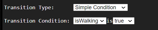
Simple Condition
The transition will trigger when the animation controller input is true or false (depending how you set it). The animation controller inputs you specified as bools will appear in the Transition Condition drop down list. For more info on how to create these inputs, see the Animation Controller Input Editor.
Scripted Condition
The transition will trigger if the code you insert in the editor evalutes to true upon runtime. The code is expected to be in C++ and has access to a variable called
datawhich holds the animation controller input values. To access the value of an input namedmy_bool_input, you must do the following:bool value = bool(data.get<int32_t>(”my_bool_input”, 0));![[object Object]](/images/docs/7536a2a1-c21c-4d83-9e0f-ced688f64d18/image-8fafcb8a-756d-4ddd-968e-9d1b9eeb238a.png)
Delete Transition Between States
- Click on the transition then press Delete.
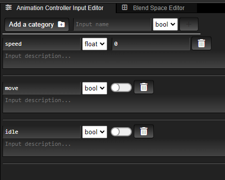
Animation Controller Input Editor
The Animation Controller Input Editor is where you can edit animation controller inputs, which can be used within your animation graph. They will show up in the animation controller component that references your animation graph, which is where you will modify their values.
An input of type bool can be used as a transition condition between states, and an input of type float can be used as input to Blend Space 1D and 2D nodes.
![[object Object]](/images/docs/bbf6444f-c620-49a7-96c2-52cfaf15d22d/Untitled-fffc9d81-5c89-4166-b358-12891379bf15.png)
You can change these input values within the scene editor or in the code of your application, by editing the animation controller component data directly.
Animation Controller Input Editor Actions:
Create Input
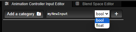
To create an input specify the input name, the input type and then press the + button on the right.
You can optionally add a category, that’s to organize your inputs in folders called categories.
Give Input Default Value
Once you created the input, you can specify its default value in the widget to the left of the trash can. This is the default value that will show up in your animation controller.
Examples:
![[object Object]](/images/docs/78349054-f109-4eb5-8559-9109120cad43/Untitled-f96d068d-459a-468e-83fd-f113f23e5d5f.png)
![[object Object]](/images/docs/78349054-f109-4eb5-8559-9109120cad43/Untitled-d4ae649d-0414-47b1-a4a6-4c9af2c92ca3.png)
![[object Object]](/images/docs/78349054-f109-4eb5-8559-9109120cad43/Untitled-2a4a58da-9d83-42af-8316-e7f1ae7b545f.png)
Delete Input
![[object Object]](/images/docs/954aa5e8-021c-432c-8fef-cb7398972ce3/Untitled-bfd35784-767c-4d3e-9f35-08d34373ae51.png)
Use bool Input in Animation Graph
A bool variable can influence a transition condition between states. When you select your transition condition, you will see the input bools you specified in the input editor, and can select one as the condition.
Use float Input in Animation Graph
A float variable can be used as input of a
Blend Space 1DorBlend Space 2Dnode. For more information on those nodes, checkTo use a float input in your State Editor (to connect it to Blend Space nodes), click on the “Grip” button and drag your input to the State Editor.
Then, in your state editor you can connect your input to the input of the
Blend Space 1Dor2Dnode.![[object Object]](/images/docs/9bdc5f3e-0e92-4037-88e9-fa544d444e33/Untitled-901270cc-c443-41eb-bc3b-e8f7e4c30c29.png)
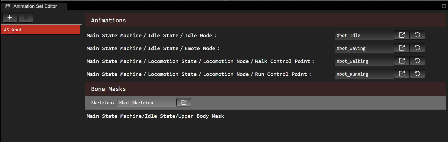
Animation Set Editor
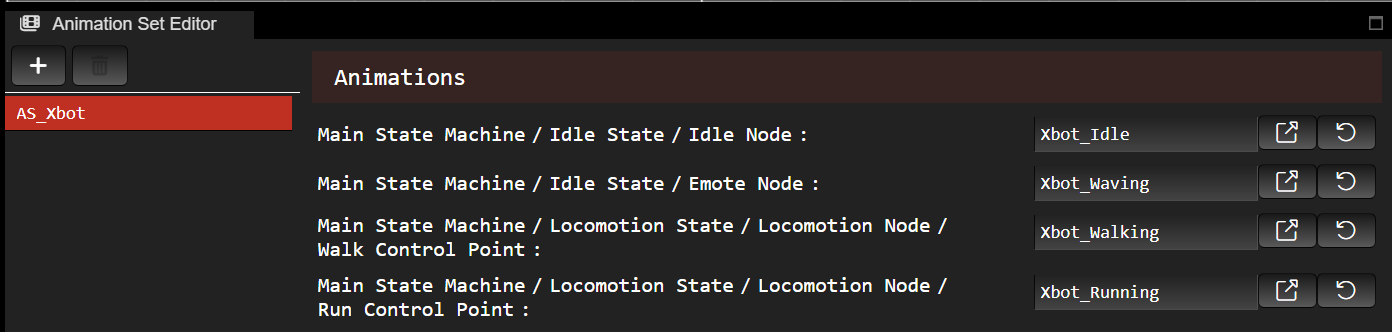
The Animation Set Editor is where you edit your animation set(s) that are compatible with your animation graph.
In your animation controller, you will have to specify your animation graph and the desired animation set you want to use it with.
Animation sets contain the animations that you want to use in your Animation Sample, Blend Space 1D and Blend Space 2D nodes of the animation graph. When you add one of those nodes (or in the case of blend spaces, when you add a control point) an animation set entry will appear.
They also contain the bone masks which you want to use in your Blend Poses node in the animation graph.
Each animation set entry is either an:
<u>animation</u>
the path of the node using your animation in your animation graph
the animation reference
![[object Object]](/images/docs/7f4d06dd-54a1-46cd-8297-af5dbec0156e/image-2f7ac961-5730-420d-9a07-eb2fd0c07346.png)
or a <u>bone mask</u>
the path of the node using your bone mask in your animation graph
![[object Object]](/images/docs/a257b803-e07a-4454-bf9c-755d97e5f05b/image-7e4e6789-d5a5-4802-983e-41bd74959fe9.png)
You cannot create entries in your animation set. This is done automatically for you when you create an Animation Sample node, when you add a control point to a Blend Space 1D or Blend Space 2D node, or when you create a Bone Mask node. All you have to do in the animation set editor is to specify the animations you want to use for those nodes. You can also select the bone mask, which will open it in the Bone Mask Editor where you will be able to edit it.
Animation Set Editor Actions:
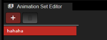
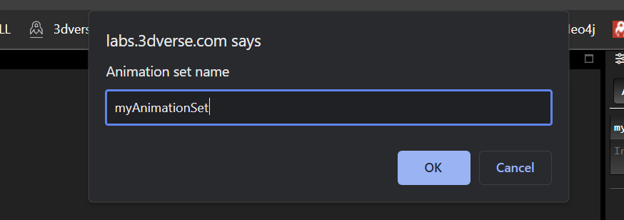
Create Animation Set
Press the + button and then specify your animation set name in the pop up and press OK.
Now you should have both:
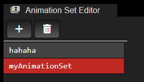
Note: when you open an empty animation graph for the first time, you will be asked to create an animation set automatically. You will always have at least one animation set associated to your animation graph.
Rename Animation Set
Unfortunately you cannot do this in the animation graph editor today. Rename your animation set in your asset browser, like you would with other assets.
Delete Animation Set
Select the animation set you want to delete (it will appear in red). Then press the trash button.
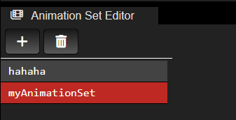
Note: If you only have one animation set, you will not be able to delete it. An animation graph has at least one associated animation set to it.
Set Animation
Open your asset browser in another tab or window and drag the animation asset to the animation set entry to set it. In the example below, the animation “Xbot_Running” was dragged to the entry “Main State Machine/Locomotion State/Locomotion Node/Run Control Point”.
Open Animation in Asset Browser
![[object Object]](/images/docs/7d139846-f671-4023-ba12-9caf7a3a2e99/image-510ead2c-b7d5-4b3f-9554-eb6bc6f28a58.png)
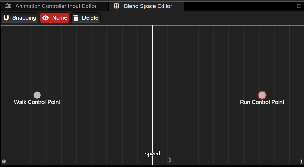
Blend Space Editor
The Blend Space Editor is the tab next to the Animation Controller Input Editor.
The Blend Space Editor is where you will edit the control points of your Blend Space 1D and your Blend Space 2D nodes.
When you click on a Blend Space node the Blend Space Editor should open automatically.
Blend Space Editor Actions:
Move Around
To move around, hold RMB or Mouse Scroll within your Blend Space Editor and move your mouse.
To zoom in and out, scroll your mouse.
Create Control Point
Right click to create control point, specify its name, then press enter.
Edit Control Point Animation
There is an animation set entry in the Animation Set Editor for each control point you create. You can modify the animation there.
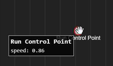
View Control Point Coordinates
Hover over the control point to see its coordinates.
Edit Control Point Coordinates
You can hold and drag the control point on the X axis (Blend Space 1D) or X/Y axis (Blend Space 2D) of your Blend Space Editor to edit its coordinates.
Delete Control Point
Select the control point by clicking on it and press Delete.
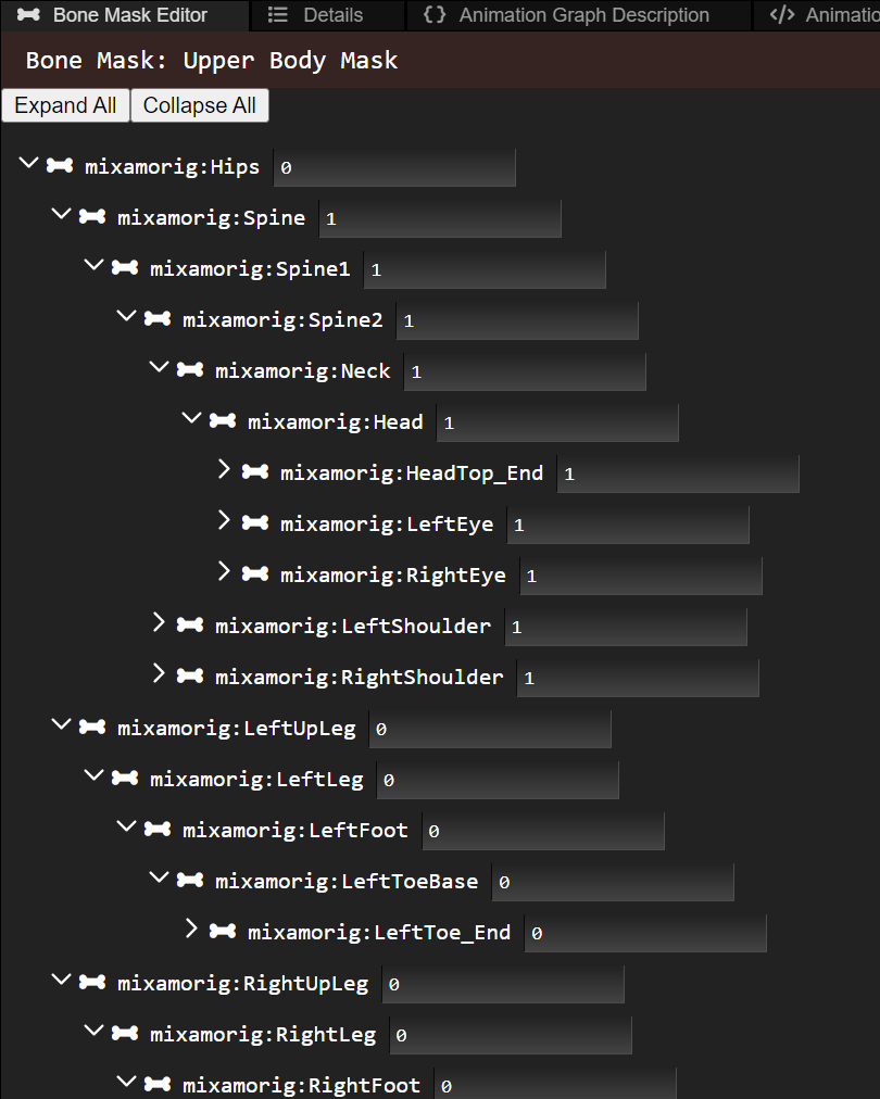
Bone Mask Editor
The bone mask editor allows you to edit a bone mask, which is a list of weights per bone. This can be used to only apply a pose on a select part of the skeleton. The weights you assign are expected to be between 0 and 1. To open the bone mask editor, either select a bone mask node in the State Editor or click on the bone mask you want to edit in the Animation Set Editor. The skeleton used is the one specified under Bone Masks in the Animation Set Editor.
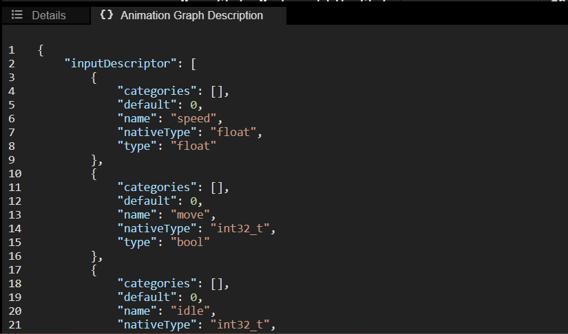
Animation Graph Description
The Animation Graph Description is the tab next to Details. It simply shows your animation graph description and is mainly a debug tool. If you have any publishing errors, they will show up here.
Animation Graph Nodes
Animation Sample
An animation sample node simply samples its given animation and outputs it.
![[object Object]](/images/docs/bbf6444f-c620-49a7-96c2-52cfaf15d22d/Untitled-d06a9c85-e46d-4f06-be7c-0f082aa08fdc.png)
![[object Object]](/images/docs/bbf6444f-c620-49a7-96c2-52cfaf15d22d/Untitled-2c8438e3-ba8d-412e-b479-d9bb4b2ace6e.png)
In the details of animation sample node you can specify things like:
- animation
- the animation for the selected animation set. This value is synchronized with the corresponding animation set entry in the Animation Set Editor.
- playback speed (float)
- start offset (float, normalized value between 0 and 1)
- this will force the sampling to start at a given offset of the animation. 0 corresponds to the start and 1 corresponds to the end.
- loop
Blend Space 1D
A blend space 1D allows you to control the blend between different animations (or control points) through a float input. It is 1D because we define control points along one axis.
Note that when you add a control point in the Blend Space Editor, you can edit its corresponding animation in the Animation Set Editor.
![[object Object]](/images/docs/bbf6444f-c620-49a7-96c2-52cfaf15d22d/Untitled-c7d220f6-6124-490e-bec0-b457b34a41da.png)
![[object Object]](/images/docs/bbf6444f-c620-49a7-96c2-52cfaf15d22d/Untitled-8cfb0b39-6de0-43ca-8a9a-b4e688fb7896.png)
In the example above, my Blend Space 1D has two control points: “Walk Control Point” which is at speed = 0, and “Run Control Point” which is at speed = 1. “Walk Control Point” and “Run Control Point” reference walk and run animations respectively.
In my scene, when I change the value of speed (in my animation controller) to 0.5, then this node will blend equally between Walk and Run animations. If I change the value of speed to 0.75, it will blend both animations but the Run animation will have a weight of 0.75, while the Walk animation will have a weight of 0.25.
![[object Object]](/images/docs/bbf6444f-c620-49a7-96c2-52cfaf15d22d/Untitled-89712f06-414b-4df4-865b-e46c0beecd6d.png)
Blend Space 2D
The idea is the same as Blend Space 1D except now we can control the blend of animations using two float inputs (which correspond to X and Y axis in Blend Space Editor).
![[object Object]](/images/docs/bbf6444f-c620-49a7-96c2-52cfaf15d22d/Untitled-624d2758-88e4-484c-86c9-89e10094ffe6.png)
![[object Object]](/images/docs/bbf6444f-c620-49a7-96c2-52cfaf15d22d/Untitled-0f4af320-81d3-43e5-9e5b-44c054cbe555.png)
![[object Object]](/images/docs/bbf6444f-c620-49a7-96c2-52cfaf15d22d/Untitled-feec31ed-ab00-4dcd-b5d8-bb759917fa10.png)
State Machine
A state machine node is… a state machine! When you click on a state machine node, its state machine will open in the State Machine Editor above the State Editor. The output pose of a state machine node is the output of its state machine.
![[object Object]](/images/docs/bbf6444f-c620-49a7-96c2-52cfaf15d22d/Untitled-e3a49570-09e1-4df2-b7f3-82ea850fe7ba.png)
![[object Object]](/images/docs/bbf6444f-c620-49a7-96c2-52cfaf15d22d/Untitled-5be1f714-cbda-4450-82e9-4e45b4d25334.png)
Blend Poses
Blend Poses allows you to blend different poses and give them different weights.
![[object Object]](/images/docs/bbf6444f-c620-49a7-96c2-52cfaf15d22d/Untitled-9f9abd6a-0d7d-4d38-b8a4-a92bd6643d42.png)
You can give the Blend Poses an arbitrary amount of poses to blend with, and then specify the pose weights. Pose weights should be between 0.0 and 1.0. Bone mask is optional and can be specified if you’d like to give bone weights for that animation layer. If bone mask has no input, then each bone will have a weight of 1.
Each subsequent pose/weight/bone mask layer will override the previous layers.
![[object Object]](/images/docs/bbf6444f-c620-49a7-96c2-52cfaf15d22d/image-f7bad3ba-5913-4b1b-a104-932e067a2136.png)
To create a bone mask node to assign to the Blend Poses node, right click on State Editor and select the Bone Mask node and give it a name. To edit the bone mask, select the node and the bone mask editor will open. You will be able to assign weights per bone there.
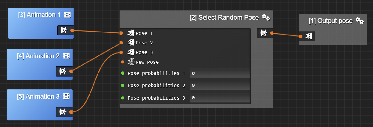
Select Random Pose
Select Random Pose takes an arbitrary amount of input poses and will select to output one of those poses at random. When a state begins to run, the random input is chosen. The random input will stay the same until that state transitions to another one. Then, when some other state transitions to our state again, the random input will be recalculated.
![[object Object]](/images/docs/bbf6444f-c620-49a7-96c2-52cfaf15d22d/Untitled-0e3f0adb-73f9-47b4-99a1-b78eff418816.png)
You can also specify Pose probabilities. If specified, probabilities are between 0.0 and 1.0 and should all add up to 1.0.
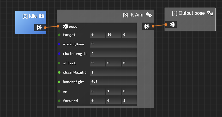
IK Aim
IK Aim acts on a single bone (the aiming bone) to orient, or aim, a forward vector (in bone local space) to a target position (in world space). This can be used to aim a head bone so it looks at a target or to aim a weapon. The up vector (in bone local space) is also used to keep the bone oriented in the same direction as the world up (0, 1, 0). The node also exposes an offset (in bone local space) from where the forward vector should aim the target (this can be used to aim the “eyes”, which could be relative to the neck bone).
The chain length is the number of bones that are corrected by IK.
The chain weight is the weight given to whole IK process, allowing blending in and out.
The bone weight is the weight given to IK for each bone of the chain (except for the last bone which is 1). This directly affects correction spreading.
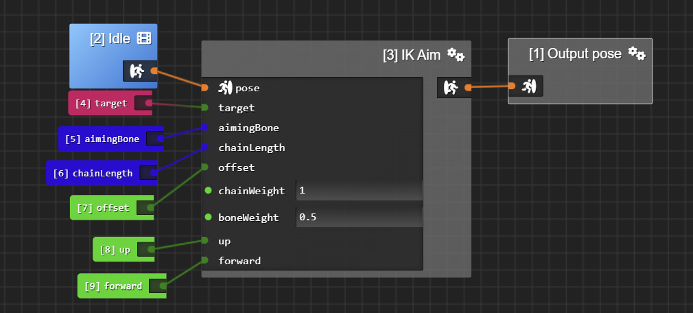
Target can be either a vec3 input or an entity input. If target is an entity input, the IK Aim will try to aim at this target entity’s world space position each frame.
Aiming bone expects a uint, i.e. the aiming bone index.
All of the inputs (except for pose) can either be animation controller inputs or hard coded in the node.
To help debugging the up and forward vectors, then make sure you “enable debug lines” and “draw IK” in the scene settings. This will draw the up vector in green and forward vector in blue (in world space) from the aiming bone’s location.
IK Two Bone
An IK Two Bone node is used to animate a chain of three bones (startBone, midBone and endBone) that remains on the same plane: like arms (shoulder, elbow, wrist) or legs (hip, knee, ankle). The end bone will try to reach a target position and the other bones will position themselves in response. There can be intermediate bones between the start, mid and end bone. However these bones must be part of the same hierarchy, aka ancestors of the last leaf bone (=endBone).
The pole vector defines where the direction the middle bone should point to. It should be specified in model space of the skeleton.
Weight is the weight given to whole IK process, allowing blending in and out.
Twist angle additionally rotates the IK chain around the vector defined by start-to-end bone vector.
Soften allows the chain to gradually fall behind the target position. It can prevent the bone chain from snapping into final position, softening the final degrees before the bone chain becomes flat.
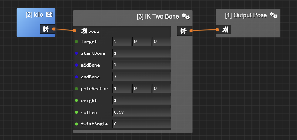
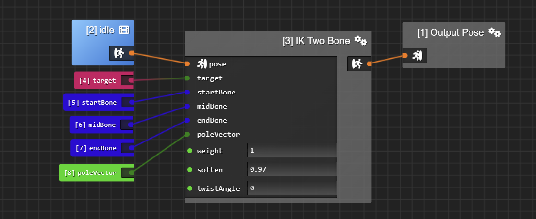
Target can be either a vec3 input or an entity input. If target is an entity input, the IK Two Bone will try to reach this target entity’s world space position each frame.
Start, mid and end bone expect a uint, i.e. the bone index.
All of the inputs (except for pose) can either be animation controller inputs or hard coded in the node.
To help debugging the pole vector, then make sure you “enable debug lines” and “draw IK” in the scene settings. This will draw the pole vector in red (in world space) from the mid bone’s location.