Renderer Architecture
Purpose
The FTL Engine is the rendering core of the 3dverse Cloud Renderer. Its role is simple to state but complex to achieve: take the live scene model hosted in a rendering session and transform it into video frames that can be streamed back to clients.
Unlike traditional engines, FTL is entirely data-driven and designed for the cloud from the start. The engine does not hard-code a rendering pipeline. Instead, it assembles one at runtime based on assets and components:
- Cameras define what to see.
- Render Graphs define how it is processed.
- Materials define what each surface emits.
Together, these three elements form the conceptual backbone of rendering in 3dverse.
Cameras
In 3dverse, a camera is not a built-in object type. It is simply an entity that gains the ability to render when it carries two components:
- A lens component – perspective or orthographic – that defines how the scene is projected.
- A camera component – which references a render graph asset and provides parameter values.
Without both, the entity is inert; with them, it becomes a functioning viewpoint into the scene.
This maps directly to real-world intuition.
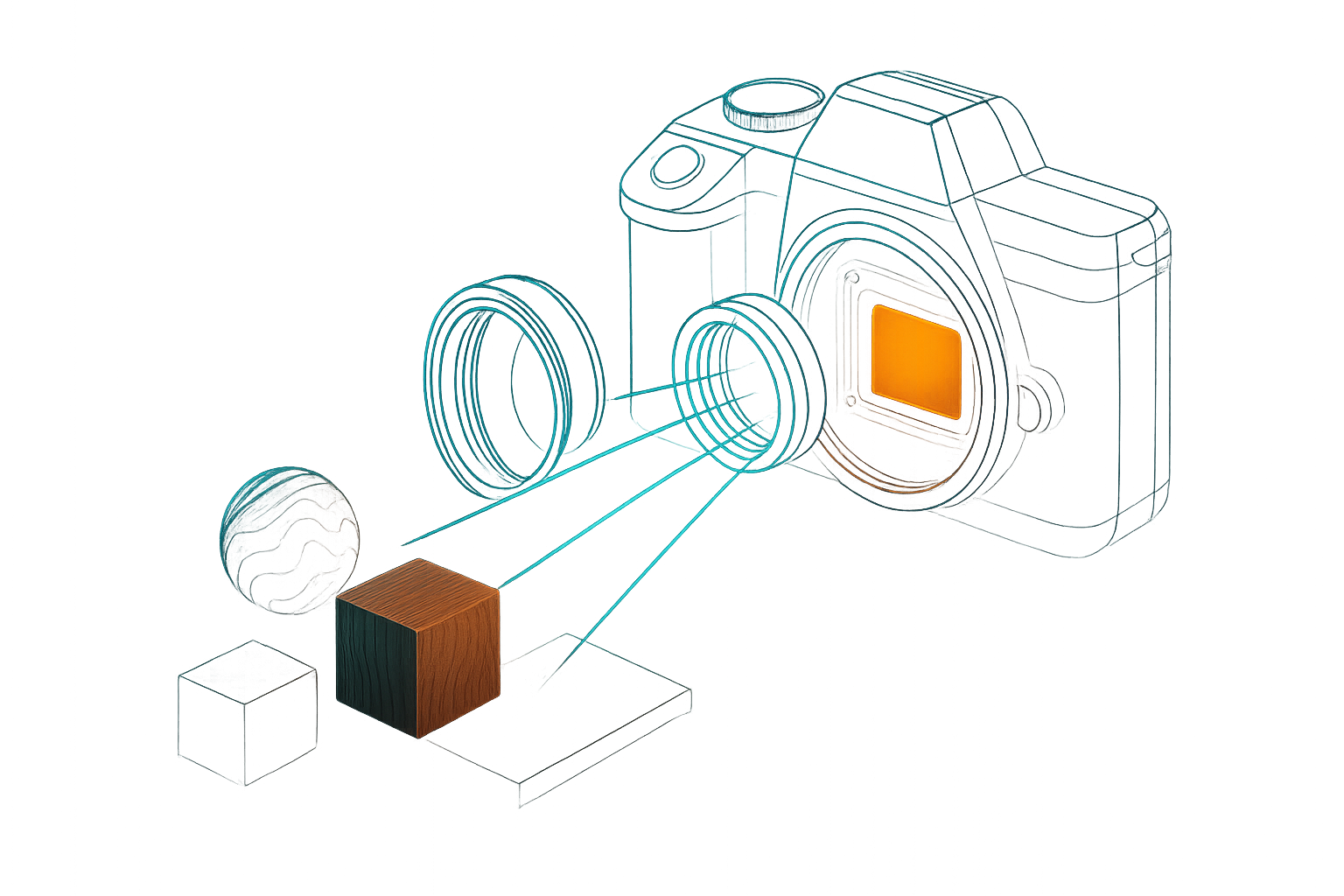
- The entity is like the camera casing – an empty shell.
- The lens provides the optics – wide angle, telephoto, or orthographic.
- The camera component links the entity to the render graph – the internal processing pipeline.
This separation makes cameras modular and declarative. A rendering session can host multiple cameras, each with its own lens and render graph, all operating independently within the same scene.
Render Graphs
A render graph is an asset that defines the rendering pipeline to run on the GPU. It specifies the render targets, passes, and nodes that transform scene data into images.
Conceptually, a render graph plays the role of the sensor and processing unit inside a digital camera. Just as a real sensor only captures certain wavelengths and the processing pipeline decides how to merge or filter them, the render graph determines:
- Which outputs will be produced (the “channels” of rendering).
- Which steps will be run in sequence to process them.
- How materials must write into those outputs to be valid.
Because render graphs are assets, they are:
- Data-driven – authored and stored like any other asset.
- Hot-reloadable – changes propagate without restarting sessions.
- Flexible – multiple cameras in the same scene can reference different render graphs, producing very different outputs from the same underlying entities.
In short, the render graph is the programmable imaging pipeline that sits between the camera’s viewpoint and the materials that describe each surface.
Materials
Materials define how surfaces appear when captured by a camera. They are authored as shaders (via the Shader Graph Editor) that compute the values a render graph expects.
Think of materials as the physical properties of real-world objects. A metal surface, wood, or glass each emit different signals. The render graph, acting as the sensor + processing pipeline, can only detect specific outputs. If a material does not emit the expected outputs, the render breaks — unlike a real camera, which would simply show black.
Rule of thumb: author materials for the render graph you plan to use.
How materials participate in rendering
- When a camera executes its render graph, the pipeline invokes material shaders for visible geometry.
- Depending on the graph, this may happen in two ways:
- A graph-selected shader shades an entire batch.
- Each entity’s material shader is used directly (the common case).
Scope of authoring
- End-user focus is on material shaders (vertex + fragment for the default pipeline).
- Materials must follow the conventions of their render graph — the names and semantics of its outputs.
Defaults
3dverse provides a default render graph and a default PBR material shader that are designed to work together.
- The default render graph is configurable.
- The PBR material shader is extensible: you can customize how properties (albedo, roughness, emissive, etc.) are computed, while the shader always writes valid outputs for the default graph.
In essence, materials describe what surfaces emit, while the render graph defines what the camera can detect and how it processes it. Together with the lens and camera component, they close the loop from scene data to final frames.
How It All Fits Together
Cameras, render graphs, and materials are not isolated concepts — they form a closed loop that transforms the scene into a final frame.
-
Scene entities carry meshes, transforms, and materials.
- Materials define the surface outputs they emit.
-
A camera entity (lens + camera component) sets the viewpoint and chooses a render graph.
- The lens determines the projection.
- The camera component provides parameters and selects which render target to stream back.
-
The render graph runs as the pipeline.
- It defines the render targets, passes, and nodes to process the scene.
- At draw steps, it invokes the materials of visible entities to shade surfaces.
-
The engine resolves this into render targets, from which the camera chooses one to encode and stream back to clients.
This model makes rendering in 3dverse modular and explicit:
- Change the camera → you change the viewpoint or projection.
- Change the render graph → you redefine the pipeline and outputs.
- Change the materials → you alter how surfaces appear within that pipeline.
Because all three are assets or components, they can be authored, reused, and hot-reloaded like any other part of the system. Multiple cameras in the same scene may even use different render graphs simultaneously, producing varied outputs (e.g. one for display, another for analysis).
Together, these pieces ensure that rendering in 3dverse is both flexible and data-driven: every frame is the product of explicit assets and components, not hard-coded rules inside the engine.
From Render Graph to Client Canvas
Rendering does not stop at producing GPU render targets. The client defines a canvas — the final surface to be streamed back as video. This canvas can be divided into viewports, each bound to a camera.
- Each viewport references a camera entity.
- The same camera can drive multiple viewports, even across different clients and canvases.
- For each viewport, the camera runs its render graph and writes into that viewport region.
- The engine composites all viewports into the canvas.
Once the canvas is complete, it is passed to the video encoder, which produces a compressed frame stream. That stream is sent back to the client, which can:
- Display the canvas as a whole.
- Split its viewports into different UI regions (e.g. a main view and a minimap, or multiple perspectives side by side).
Defaults and Safe Starting Point
While the system is highly flexible, most applications do not need to start from scratch. 3dverse provides built-in defaults that cover common use cases:
-
A default render graph Configurable but production-ready, it defines a complete pipeline with sensible outputs (color, depth, etc.) and post-processing steps.
-
A default PBR material shader Extensible, it lets you customize how material properties such as albedo, roughness, or emissive values are computed — while always writing valid outputs for the default render graph.
These defaults ensure that developers can immediately create scenes and render them without designing a pipeline first. From there, you can iterate incrementally: swap in a custom material shader, adjust render graph parameters, or eventually author your own graph for advanced control.
With these building blocks in place, the FTL Engine can transform the data-oriented scene model into rendered frames that stream seamlessly to clients — all while remaining fully cloud-native and data-driven.