Preparing a Scene for Live Data
Before connecting a live data source, make sure the scene is structured so it can be driven correctly. The goal is to preserve the mechanical structure of the machine, so that live data can naturally control it.
Start from the right source
If your assets come from simulation software such as Siemens Tecnomatix Process Simulate, Visual Components, ABB RobotStudio, FANUC ROBOGUIDE, KUKA.Sim, DELMIA or Rockwell Emulate3D, they are often already organized around the machine kinematics and can usually be exported directly. Reusing that hierarchy is generally preferable to exporting from the original CAD assembly — the mechanical structure has already been established there, and rebuilding it later is the expensive part.
If you are exporting directly from a CAD package such as SolidWorks, Siemens NX, Creo, Inventor or Revit, keep the assembly as close as possible to the real machine's structure, and make sure moving parts are organized into a meaningful hierarchy.
Preserve the mechanical hierarchy
The scene hierarchy should reflect how the real machine moves. Each moving assembly becomes its own parent entity, with child entities representing the parts that follow its motion:
RobotBase
 └── Shoulder
      └── Elbow
           └── Wrist
                └── Grippers
When a parent entity moves, all of its children automatically follow — which is what makes it possible to animate an entire mechanism by updating only a few transforms.
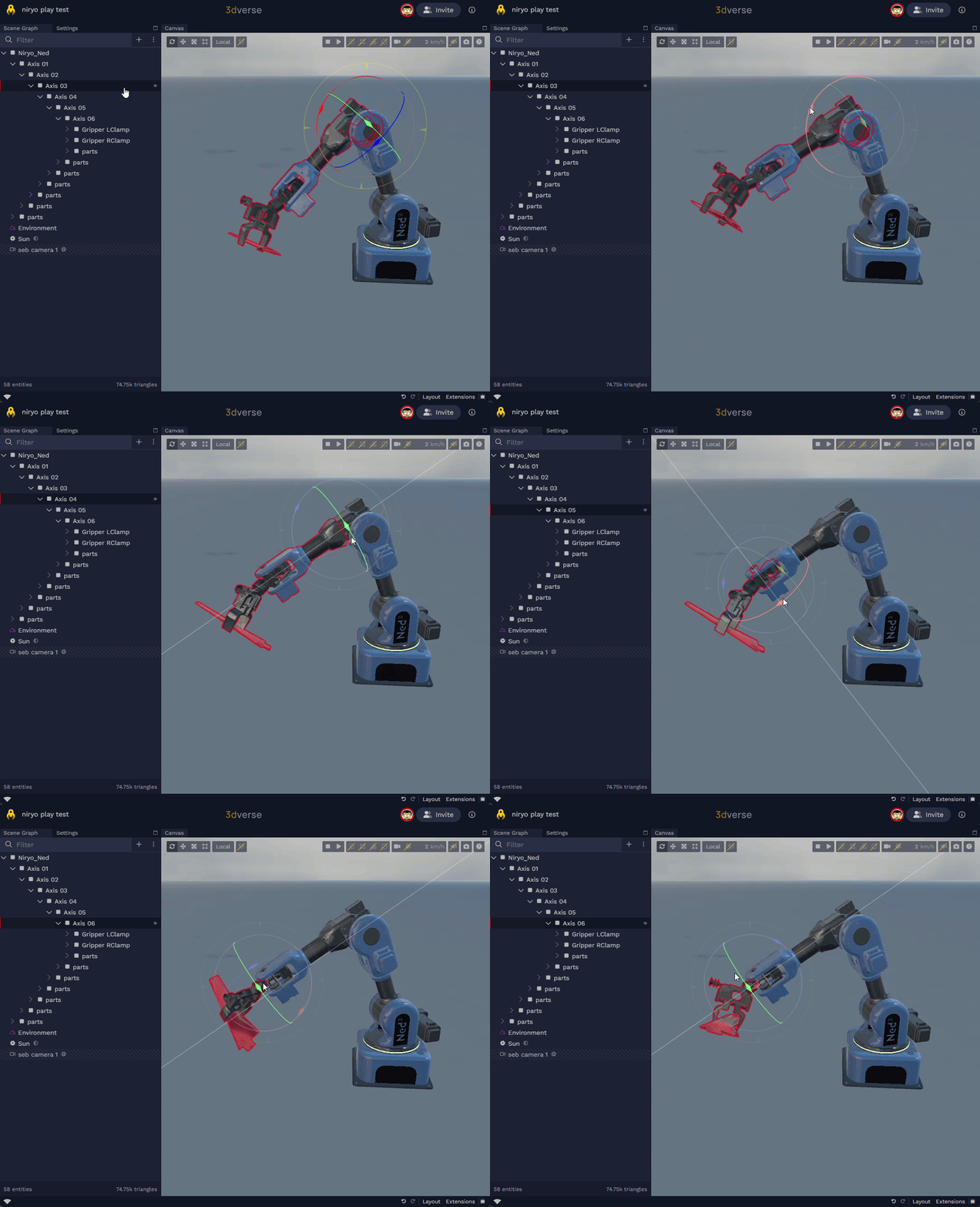
A CAD export usually gives you the opposite: hundreds of parts flat under the root, each with its own world-space transform and no relationship between them. Group related parts under the part that drives their motion, and keep the hierarchy shallow but meaningful — avoid over-nesting, but make sure every parent–child link reflects a real mechanical relationship.
Place pivots correctly
Every rotating or translating component should have its pivot aligned with the real mechanical axis:
- Re-align local origins to their actual hinge or rotation centers.
- Avoid arbitrary global pivots — everything rotating around the world origin — unless the whole system really does move as one.
Incorrect pivots are one of the most common causes of unrealistic motion, and are much easier to fix before the scene is imported.
Use meaningful names
Entity names are the join key between your scene and your data, so what matters most is that they are stable,
unique, and not tool-generated. Names like Part_00034 or Body_12 are meaningless outside the design tool and
frequently change on the next export — and a name that changes breaks every mapping written against it. Naming parts
after what they are (axis-3, gripper-left, conveyor-in) is the part of this that is genuinely in the modeler's
hands.
Whether those names also match the identifiers your stream carries — joint names, PLC tags, axis numbers, device ids — is a bonus, not a prerequisite. On a real installation the tag namespace belongs to the automation team and predates the 3D model, and nobody renames a control system to match a CAD assembly. The mapping is the seam that absorbs the mismatch: alignment only decides which addressing strategy you use.
| Situation | Strategy |
|---|---|
| Names already match the ids — one machine, a model you control | byName pattern, no configuration at all |
| Deterministic difference — a prefix, a case rule, a separator | byName function form |
| No relationship, closed population | byUuid table |
| No relationship, large or changing population | resolve, backed by an equipment or tag register |
Where the names do line up, a mapping addresses entities with nothing but a pattern:
entities: {
    byName: "axis-{id}";
}
See resolving entities for all four strategies. One case where alignment is realistically obtainable: a model coming from a simulation tool that was itself built from the control project often already carries the robot, axis and signal names from that project — worth preserving on export for exactly this reason.
Know the exceptions
Most industrial equipment can be represented by a parent–child hierarchy, because motion flows in one direction: from a part to the parts it carries. Some mechanisms require additional logic, including:
- closed kinematic loops
- delta robots
- scissor lifts
- conveyors
- chains
- fluids
These are covered in driving mechanisms. Structure the rest of the model as a hierarchy anyway, and treat these as the exceptions they are.
Validate before writing mappings
Before connecting a live data source, in the Editor's Scene Graph extension:
- Rotate joints manually and confirm everything below them follows, the way it does on the real machine.
- Verify the pivots — each one on its real mechanical axis.
- Verify the hierarchy — every parent–child link reflecting a real mechanical relationship.
- Verify the entity names against the identifiers your stream will carry.
If the scene behaves correctly manually, it will usually behave correctly when driven by live data — and all four are much cheaper to fix now than after a mapping is written against them.
Next steps
- Driving mechanisms — the recommended approach for each kind of mechanism.
- Quickstart — get data flowing into the scene you just prepared.